




Call Us Now
Jannie Ye: +86 17728636936
Jenny: +86 18127522581
Miriam: +86 15018897468

Views: 0 Author: Site Editor Publish Time: 2026-11-13 Origin: Site
Excavator downtime caused by drive system failures immediately impacts project timelines and fleet profitability. Mechanics often observe symptoms in the tracks or swing function, but these issues frequently originate upstream in the hydraulic system. Misdiagnosing the root cause of a drive failure is a common trap that leads to procuring incorrect, expensive components and prolongs machine inactivity. Accurately evaluating and sourcing replacement excavator hydraulic parts requires precise diagnostic skills. You must understand how hydraulic flow and pressure translate into mechanical force through the travel and swing drive systems. Fixing a mechanical gear without addressing upstream pressure anomalies guarantees repeat failures. Fleet managers need a clear framework to isolate hydraulic faults from mechanical wear.
Drive system efficiency relies on a matched relationship between upstream hydraulic generation (pumps/valves) and downstream mechanical execution (motors/gearboxes).
Premature failure in an excavator final drive or swing drive gearbox is frequently a symptom of contamination or pressure irregularities originating in the main hydraulic circuit.
Evaluating replacement components requires analyzing pressure tolerances, volumetric efficiency, and material durability rather than just upfront cost.
Successful implementation of new hydraulic parts demands strict contamination control and system recalibration to prevent cascading failures.
A healthy hydraulic-to-drive relationship requires consistent pressure, optimal fluid viscosity, and zero internal bypassing. When these baseline requirements falter, downstream mechanical components suffer. You must evaluate the entire hydraulic architecture to maintain machine performance. We often see mechanics replace a blown track motor only to have the new one fail a week later because they ignored the upstream pressure spikes. The system operates as a closed loop where a failure in one zone rapidly contaminates the rest.
The main pump acts as the heart of the machine. It converts engine horsepower into hydraulic flow and pressure. Modern excavators utilize axial piston pumps with variable displacement. This mechanism adjusts fluid flow based on the immediate load demands of the drive systems. When you push the travel levers, the pump increases flow to move the machine. The swashplate angle inside the pump dictates how much fluid moves through the system per revolution.
An excavator hydraulic pump relies on tight internal tolerances. Wear on the valve plate or piston shoes reduces volumetric efficiency. Signs of pump degradation often mimic drive motor failures. Look for aeration, cavitation, or metal shavings in the hydraulic filters. If the entire machine feels sluggish, the main pump is likely the culprit. Field testing involves deadheading a function and reading the main relief pressure. If the gauge shows a 500 psi drop from factory spec, your pump is bypassing internally. You cannot tune out mechanical wear with relief valve adjustments.
The control valve functions as the central nervous system of the excavator. It directs pressurized fluid to the travel, swing, and implement circuits. Inside the valve block, machined spools shift to meter hydraulic flow. These spools operate under extreme pressure and require precise clearances. The valve block also houses secondary relief valves that protect individual circuits from pressure spikes during heavy digging or sudden stops.
Internal leakage within an excavator main control valve causes sluggish travel or weak swing performance. Fluid bypasses the intended circuit and returns to the tank. Evaluating this component requires deciding between a rebuild or a full replacement. Rebuilding works if the spool bores remain unscored. Severe internal wear mandates purchasing a complete replacement assembly. We check pilot pressures first. If pilot pressure is good but the main spool barely shifts, the valve block is usually scored. Replacing individual spools rarely works because the cast iron bore wears alongside the steel spool.
Hydraulic fluid transmits power, lubricates moving parts, and dissipates heat. Thermal breakdown accelerates the wear of seals and sliding surfaces. Degraded oil loses its viscosity. This allows metal-to-metal contact inside the pump and motors. When oil thins out, it slips past the rotary group clearances, generating even more heat in a destructive cycle.
Oil coolers and bypass valves maintain safe operating parameters. They protect high-precision components from catastrophic heat damage. Routine fluid analysis identifies thermal degradation early. Maintaining optimal fluid viscosity prevents premature failure across the entire hydraulic circuit. When oil temps exceed 180°F, seal life drops exponentially. Check the cooler fins for debris buildup before assuming a component is failing. A clogged radiator often masquerades as a failing hydraulic pump.
Troubleshooting the travel system requires breaking it down into hydraulic and mechanical sub-components. This isolation improves diagnostic accuracy and informs better procurement decisions. You must separate fluid power issues from mechanical gear failures. A systematic approach prevents throwing expensive parts at a misdiagnosed problem.
The hydraulic travel motor receives high-pressure fluid from the control valve. It converts this fluid power into rotational force. Inside the motor, pistons push against a swashplate. The angle of this swashplate determines the travel speed. A steeper angle provides high torque for climbing. A shallower angle delivers high speed for flat terrain. The motor also houses the counterbalance valve, which prevents the machine from running away when traveling downhill.
Sourcing a replacement requires verifying specific technical specifications. You must match the displacement, pressure rating, and port configuration. Installing a mismatched motor causes tracking deviations. The machine will pull to one side during operation. We always verify the two-speed function during diagnostics. If the motor won't shift into high speed, the pilot line might be blocked, or the displacement piston is seized. Never assume the motor is dead without checking the pilot pressure feeding the two-speed spool.
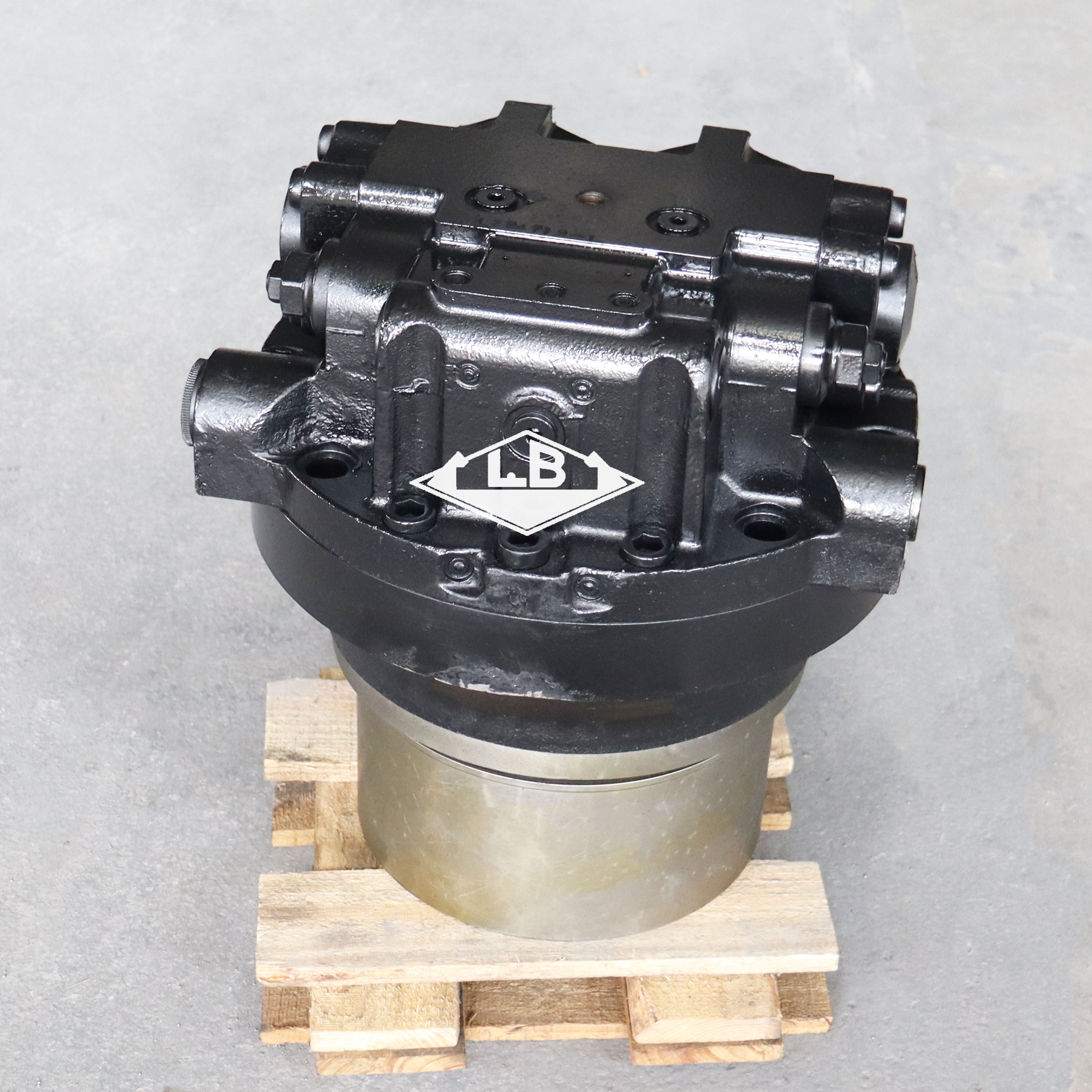
The mechanical handoff occurs where the travel motor shaft engages the planetary gear set. This gear set lives inside the excavator final drive. The final drive multiplies torque to move heavy tracks across high-resistance terrain. It reduces the high-speed rotation of the motor into low-speed, high-torque output. The sun gear drives the planetary gears, which walk around the ring gear to turn the hub.
Critical fluid separation exists within this assembly. The motor uses hydraulic oil, while the final drive hub uses heavy gear oil. A floating seal separates these two fluids. Catastrophic risks arise if this seal fails. Hydraulic oil floods the gear hub, blowing out the main cover plate. Conversely, gear oil can contaminate the main hydraulic system. We recommend draining a small sample of gear oil every 500 hours. If it looks milky or smells burnt, you have a seal problem. Catching a leaking floating seal early saves the entire planetary gear set from destruction.
The center joint connects the upper structure plumbing to the lower track frame. It serves as the high-wear link between the main control valve and the travel motors. Rotary seals inside the joint separate the high-pressure travel circuits. The center barrel remains stationary with the undercarriage while the outer housing rotates with the cab.
Internal leakage here causes cross-port contamination. High-pressure fluid bleeds into the low-pressure side. This results in significant performance loss. Mechanics frequently misdiagnose a bypassing center joint as a failed travel motor. Always test the center joint before replacing track motors. Cap the lines at the swivel and stall the travel function. If the pressure holds, the swivel is good, and the motor is bad. Resealing a center joint takes a few hours and costs a fraction of a new travel motor.
Distinguishing between a weak pump, a bypassing swivel, and a failing final drive saves time and money. Case drain line inspections provide the definitive test for internal wear. High case drain flow indicates excessive internal bypassing within the motor. You measure this by disconnecting the case drain line and running the fluid into a bucket while stalling the tracks.
Symptom | Probable Root Cause | Diagnostic Action |
|---|---|---|
Machine tracks to one side | Uneven motor wear or center joint seal failure | Perform case drain test on both travel motors. |
Overall sluggish movement | Main hydraulic pump degradation | Check main relief pressure at the pump. |
Grinding noise from tracks | Planetary gear failure in final drive | Drain gear oil and inspect for metal fragments. |
Loss of travel power when hot | Thermal breakdown or internal motor scoring | Measure case drain flow at operating temperature. |
Oil leaking from sprocket | Floating seal failure | Remove track and inspect final drive hub face. |
A healthy swing system exhibits smooth acceleration, precise braking, and zero gear backlash. Evaluating these performance metrics helps isolate wear. The swing circuit endures massive inertial loads during operation. Stopping a fully loaded bucket mid-swing generates immense pressure spikes that the hydraulic system must absorb.
The hydraulic swing motor converts fluid power into rotational force. This force moves the excavator's massive upper house. The motor integrates anti-cavitation valves and crossover relief valves. These valves protect the internal components during sudden stops or heavy side-loading. When you release the joystick, the crossover relief valves bleed off the pressure spike to prevent the motor shaft from snapping.
Evaluating swing motor efficiency requires measuring internal leakage rates. Excessive leakage causes the upper structure to drift on slopes. It also results in weak swing acceleration. Case drain testing remains the most accurate diagnostic tool for this component. We hook a flow meter to the case drain line. If the flow exceeds the manufacturer's spec by more than 10%, the motor needs a rebuild. A drifting cab is a major safety hazard on job sites and requires immediate attention.
The excavator swing drive gearbox reduces the high-speed rotation of the swing motor. It delivers the high-torque rotation required by the swing bearing. The planetary gears and pinion shaft handle extreme mechanical stress. The pinion gear meshes directly with the massive swing bearing bolted to the undercarriage.
Shock loads severely impact the gearbox. Hitting an immovable object with the bucket sends destructive force back through the pinion shaft. Inspection protocols must include checking gear wear, bearing play, and lubrication breakdown. Contaminated gear oil accelerates wear on the planetary carrier. We pull the dipstick on the swing drive regularly. If the oil is thick with brass or steel flakes, the planetary gears are disintegrating. You must pull the entire gearbox and inspect the swing bearing teeth for collateral damage.
Choosing replacement parts involves navigating trade-offs between different tiers of components. You must balance immediate availability against long-term reliability. A structured evaluation prevents installing substandard parts on critical fleet assets.
Original Equipment Manufacturer (OEM) parts offer guaranteed specifications. They ensure perfect fitment but carry a high upfront cost. Aftermarket alternatives provide lower costs but feature variable quality. You must vet aftermarket suppliers rigorously. Remanufactured components offer a viable solution for older fleet assets. They balance cost and reliability. Focus on warranty provisions and core exchange requirements when buying remanufactured parts. Ensure the rebuilder replaces all wear items, not just the failed components. We always ask for the dyno test sheet when buying a remanufactured pump. If they can't provide one, we don't buy it.
Component Tier | Primary Advantage | Primary Disadvantage | Best Application |
|---|---|---|---|
OEM | Guaranteed fit and factory performance | Highest initial capital outlay | Newer machines under factory warranty |
Premium Aftermarket | Excellent balance of cost and performance | Requires vetting supplier certifications | Mid-life fleet assets running daily production |
Remanufactured | Sustainable option with OEM cores | Core return logistics can be complex | Older machines where new parts exceed asset value |
Installing a high-efficiency new pump into an aging system carries severe risks. The new pump generates factory-spec pressure. This sudden pressure increase often blows out older seals in the travel or swing motors. The entire hydraulic circuit must remain balanced. Match component tolerances carefully. If you replace one travel motor, evaluate the health of the opposite motor. Uneven efficiency between left and right motors causes tracking issues. System matching prevents cascading failures across the machine. We recommend replacing travel motors in pairs on machines with over 6,000 hours.
Introducing contamination during installation destroys new components instantly. Dirt entering an open hydraulic line acts like grinding paste. Strict mitigation steps are mandatory during part replacement.
Cap all hydraulic lines immediately upon disconnection to prevent dirt ingress.
Flush the entire hydraulic system if the previous component suffered a catastrophic mechanical failure.
Replace all return and pilot filters before starting the machine.
Verify pilot pressures and main relief settings post-installation using calibrated gauges.
Bleed trapped air from the pump case before cranking the engine to prevent dry starts.
Demand ISO-certified testing data for aftermarket hydraulic parts. Reputable suppliers provide hydraulic dyno-testing reports with every pump or motor. These reports verify volumetric efficiency under load. Fit and finish matter significantly. Ensure mounting patterns and hydraulic port orientations match your current machine serial numbers. Incorrect port orientations require custom hose routing. This causes costly downtime and introduces potential leak points. We check the spline count on the output shaft before accepting delivery. A mismatched spline means the motor won't mate with the gearbox.
Developing a robust procurement strategy requires understanding component lifecycles. You must align your purchasing decisions with expected operating hours and vendor reliability.
Major components exhibit predictable lifespans under standard duty conditions. Hydraulic pumps typically last between 8,000 and 10,000 hours. Final drives require resealing around 5,000 hours and full rebuilds near 8,000 hours. Swing gearboxes often exceed 10,000 hours if gear oil is maintained. Severe duty conditions drastically reduce these benchmarks. Working in highly abrasive environments or running hydraulic hammers accelerates wear. Adjust your maintenance schedules and replacement budgets based on actual site conditions. We see final drives fail at 3,000 hours in deep mud applications because the floating seals get packed with abrasive dirt.
A strong vendor warranty covers progressive damage, not just the replacement part. If a defective new pump sends metal through the system, the warranty should cover system flushing and downstream repairs. Demand documentation before issuing a purchase order. Request dyno-testing certifications and material composition reports. Trustworthy vendors provide transparent engineering support. They help you match the right component to your specific machine serial number. We look for suppliers who ask for the machine's serial number upfront. It shows they understand the subtle engineering changes between production years.
Conduct a case drain test on your current machine to establish a baseline for motor health.
Review your machine's hydraulic schematic to identify potential cross-contamination points like the center joint.
Implement a strict fluid analysis program to catch thermal breakdown and metal wear early.
Demand dyno-testing reports from your supplier before purchasing aftermarket hydraulic pumps or motors.
A: Isolate the symptoms. Track-specific weakness or grinding noises point directly to the final drive or travel motor. If the entire machine exhibits sluggish movement, weak swing, and slow implement speeds, the main hydraulic pump is likely failing.
A: Yes, it is possible. However, you must verify the integrity of the splined shaft and the planetary gears first. Installing a new motor into a damaged gearbox will quickly destroy the new motor's output shaft.
A: Premature failure usually stems from a lack of gear oil maintenance. Severe shock loading, like using the bucket to sweep heavy debris, damages the planetary gears. Excessive swing bearing wear also misaligns the pinion shaft, accelerating gearbox failure.
A: Tracking issues have several potential causes. Begin by checking track tension. If tension is even, investigate main control valve spool wear, a bypassing center joint seal, or uneven internal wear between the left and right travel motors.
A: Acceptable leakage varies by machine size and pump design. Generally, case drain flow should not exceed 5% to 10% of the pump's total output volume. Measure this flow via the case drain line at operating temperature to determine internal wear.
A: High-tier aftermarket parts are highly reliable. However, quality varies by manufacturer. To ensure reliability for heavy-duty applications, demand ISO certifications and hydraulic dyno-testing guarantees from the supplier before purchasing.
